|
||||
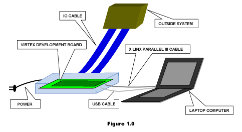
OUR SERVICES » RAPTOR/ISDRaptor/ISDRaptor/ISD is an In System Developer for testing IP, Subsystems, and small ASIC’s or FPGA’s. Raptor consists of Avnet’s Virtex Development System, a PCI backplane interface (power is included on the backplane for the Virtex Board), USB cable, Xilinx Parallel III cable, Xilinx Foundation Series software, and Raptor interface software. The Virtex Development System is equipped with a variety of components. Components ranging from SDRAM’s to USB transceivers. To obtain more information refer to Virtex Development System Documentation. Furthermore, for more information on Xilinx Foundation Series software refer to Foundation Series Quick Start Guide. Raptor has two main functions, hardware testing and test bench generation. Hardware testing is the ability to test a developing design in hardware while the user is still working on the rtl code. Test bench generation is the ability to generate a test from an actively operating device within the devices system. Hardware TestingFor example, the user is working on Utopia interface and has preliminary code. The Utopia passes all of test in the simulation environment (this is never enough when serial communication is concerned). The user also has an ATM system. The Utopia is intended for this system. With Raptor the user has a distinct advantage. This advantage is using the preliminary Utopia rtl code and connecting it to the ATM system with the ability of debugging and capturing waveforms. The first step is to take the rtl code through the Raptor interface. This interface will make the appropriate rtl code for the Foundation flow. The Raptor interface consists of assigning certain rtl signals to certain IO’s on the Virtex Board. Furthermore, the user can specify which signals he or she wants to observe (output to a vcd file for viewing wave form) and which signals have a static value. Also the user can assign appropriate clock speed for the core (in this case, utopia). Raptor interface will determine if the clock speed is feasible or not based on the amount of things that are being observed (inputs or outputs can be observed). The Raptor interface will also produce the proper UCF (this is a constraint file for Xilinx Tools) file for the Foundation flow. Taking the rtl code through the Foundation flow is step two (refer to Foundation documentation for further clarification). This step should yield a bit stream file. This bit stream is then downloaded into the Virtex part in Raptor on the Virtex Board via the Xilinx Parallel III cable. The user can facilitate the appropriate IO connections depending on where the rtl core signals are connected on the Virtex Board (open IO’s; GPIO and PCI, refer to Virtex Development System Doc.). After, Raptor system is connected to the pending ATM system the core (Utopia) is ready to interact with the system. The user now has the ability to debug any issues with the design in its native environment. Depending on what signal the user wants to observe, samples are taken at the sample size specified by the user. This information is transmitted through the USB interface to the computer where the Raptor software resides. The software will then create a vcd file for later viewing. Several samples can be taken, of which several vcd files will be made. If the user chooses test bench generation, it will be constructed out of the observed signals. Test Bench GenerationUsing the same Utopia example from above, the test bench generation is a byproduct of information already gathered to make a proper vcd file. To make a proper self-checking test all dynamic IO’s have to be observed on the core. The Raptor interface would change the IO’s and recreate a new rtl file for the Foundation flow. Once the test bench has been created it can be used on a simulator of the user choosing. The user has an actual test from the actual system environment in which the core will be interacting with. This can greatly enhance the design and development process. Raptor can greatly reduce the ASIC or FPGA testing loop. There are times when an ASIC is taped out or and FPGA is burned in, and it does not work in the system it was intended too. This way the user will know if the simulation modeling of the given system is correct, create more robust test structures and ad in finding any un-simulated flaws in the design. Furthermore, the user will know if the design will work in the given system (it may not run at speed, this depend on how many IO’s are being observed and how large the design is). Features
Raptor System Block DiagramThere is a bit of overhead in the Virtex part. The overhead consists of SDRAM (control the micron SDRAM) controller SIE-USB engine and controller (controls the data transmitted and received from the computer), a flow controller for outgoing data, and IO wrapper. The IO wrapper is what holds the core, this make signal observance possible. 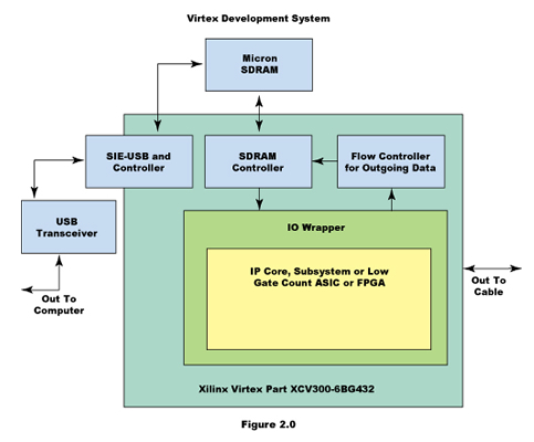 
|
| Home | About Us | Products | Design Services | Customers | Contact Us | Copyright © 2014 Experience First, Inc, All Rights Reserved. | |
| Designed by | ||